Hi Daniel,
Thanks a lot. This is so helpful. I tried both methods you suggested. The phase is correct now.
For "Shift: No", compared to the Skip Head value 127, value 129 has the max magnitude. I guess it is a zero-based system. Please correct me if wrong.
Thanks and best regards
Karen
On 27/12/2022 17:49, Karen young wrote:
> Hi,
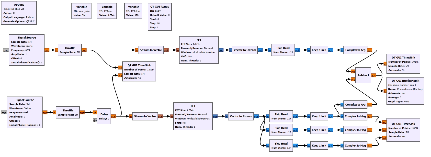
> Attached is the model I built for phase measurement.
> Since the samp_rate (5M) is 8 times of signal source freq (625k), the
> phase should be expected as shown in the table, while the measured phase
> is only correct when there is half cycle or full cycle delay.
> What can I do to make it correct?
> Delay step Expected phase delay Measured phase delay
> 0 0 0
> 1 -0.79 -1.5
> 2 -1.57 -4.7
> 3 -2.36 -1.5
> 4 -3.14 -3.14
> 5 -3.93 -1.57
> 6 -4.71 -1.57
> 7 -5.5 -1.57
> 8 0 0
Hi Karen,
I think that the problem might be with your Skip Head block. I see that,
in combination with the Keep 1 in N block, you're using it to select the
correct FFT bin in the vectors output by the FFT blocks. However, it
seems to me that you're not selecting the correct bin.
Since you're using "Shift: Yes" in your FFTs, the DC bin would be at
index 512. The bin corresponding to the positive frequency of the cosine
(you're using a real cosine, so it has a positive and a negative
frequency component, if that makes sense), would be at index 512 +
1024/8 = 640. Therefore, I think it's necessary to use 639 as the number
of items to skip.
If you used "Shift: No" in the FFTs, the the positive frequency of the
cosine would be at index 1024/8 = 128, so the number of items to skip
should be 127 rather than 129.
To make sure that you're selecting the correct FFT bin, I suggest you
look at its magnitude and compare it with a plot of the magnitudes of
all the FFT bins. This will show if you're in fact selecting the correct
bin where the maximum of the FFT is, or something else.
Best,
Daniel.